
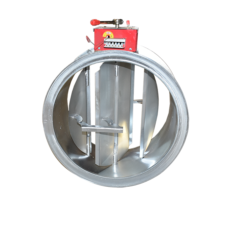
Round Fire Damper
Circular Fire Damper, Normally Open, closes at 70°C or 280°C. It is typically installed where ductwork penetrates fire-rated walls to shut off in the event of a fire. It can be equipped with a signal output device; when the temperature exceeds 70°C or 280°C, the damper closes and interlocksthe shutdown of the supply (make-up) air fan.
Technical Specification: Fire and Smoke Dampers
1. Product Definitions
Fire Damper:
Function: Prevents the spread of fire and smoke through HVAC ductwork penetrations in fire-rated assemblies (e.g., walls, floors).
Installation: Integrated into supply and return air ducts of ventilation and air conditioning systems.
Normal State: Normally Open (NO).
Activation: Automatically closes upon reaching an air temperature of 70°C, typically via a thermal element (e.g., fusible link) that releases a spring-loaded or gravity-operated closing mechanism.
Performance: Maintains fire resistance rating (stability and integrity) for a specified duration as required by local codes.
Auxiliary Function: Provides an electrical closure signal (via integral switch) upon activation.
Smoke Fire Damper (or Combination Fire/Smoke Damper):
Function: Serves a dual role: 1) Allows for the active evacuation of smoke, and 2) Prevents the spread of fire through ductwork.
Installation: Located within dedicated smoke exhaust or pressurization system ducts.
Normal State: Often Normally Closed (NC) for pure exhaust systems; can be Normally Open (NO) in dual-purpose systems.
Activation (Smoke Mode): Electrically opened (manual or automatic signal) upon fire alarm to initiate smoke extraction.
Activation (Fire Mode): Automatically closes upon reaching a smoke/gas temperature of 280°C to prevent flue-like conditions and fire spread.
Performance: Maintains its fire resistance rating while fulfilling its smoke control function.
2. Operating Principle
These life safety devices are installed within building air distribution systems. Their core operation is based on a thermal response mechanism. The most common type utilizes a fusible link designed to melt at a specific temperature (70°C or 280°C). Melting of the link releases a latch, allowing a spring or gravity mechanism to slam the damper blades shut, sealing the duct. Alternatively, some models may use shape memory alloys that change form to trigger closure. Their primary application is at points where ductwork penetrates fire compartment boundaries, maintaining the integrity of the fire separation.
3. Product Classification & Selection
A. Fire Dampers (70°C Rating)
Standard Spring-Return Fire Damper: NO, 70°C fusible link, end switch. For basic fire compartmentation in HVAC penetrations. Can interlock with HVAC fans.
Motorized Fire Damper / Regulating Fire Damper: NO, 70°C fusible link, includes a motorized actuator for remote control (e.g., from a Building Management System or Fire Panel). Used for zone control in complex systems, allowing specific areas to be isolated during a fire.
Ceiling Radiation Damper: A specialized type designed for horizontal membrane penetrations.
B. Smoke Control Dampers (280°C Rating)
Normally Closed (NC) Smoke Damper: Electrically actuated opener (24V AC/DC common) with a 280°C thermal fuse. Held closed, it opens on a fire alarm signal to exhaust smoke. Thermal closure interlock stops the exhaust fan. Standard for dedicated smoke exhaust systems.
Normally Open (NO) Smoke Fire Damper: NO for daily ventilation, closes at 280°C. Used where a single duct system is used for both daily ventilation and emergency smoke extraction (requires complex control logic).
Multi-Function / Intelligent Dampers (e.g., for Metro Systems): Feature multiple control inputs (e.g., from EMCS and gas suppression systems) and extensive feedback signalling (e.g., open/closed/trouble status). Operate on low-voltage DC power.
C. Application Notes: Grilles & Outlets
A simple air grille is sufficient if a certified smoke damper is already installed upstream in the duct.
A damper-integrated grille (e.g., motorized operated curtain damper behind a plate) is required if the damper is placed at the outlet point itself.
4. Selection Criteria
Rating: Confirm the required fire resistance duration (e.g., 1.5 hr, 3 hr) and temperature rating (70°C for HVAC, 150°C for kitchen hoods, 280°C for smoke).
Function: Define the operational state (NO or NC), actuation method (thermal, electric, motorized), and required signals (proof of closure, fault monitoring).
Interlock: For fan shutdown interlocking, dampers must be equipped with certified auxiliary switches (double-pole preferred for reliability).
Construction: Blades and frame must be constructed from galvanized steel of specified minimum thickness (e.g., 2-6mm). Bearings and operating mechanisms must be non-corrosive and operate freely. All materials must be non-combustible.
Certification: Must be tested and certified according to relevant national and international standards (e.g., UL, EN, GB).
5. Installation Guidelines
Access: A minimum 200mm clearance must be provided on the service side of the damper for inspection and maintenance.
Inspection: Prior to installation, verify the damper operates freely and shows no signs of damage.
Location: Must be installed securely within the fire-rated assembly. The distance from the damper to the wall/floor surface should not exceed 200mm.
Compartmentation: The ductwork and insulation for a minimum distance of 2.0m on either side of the damper must be constructed of non-combustible material.
Support: Dampers must be supported by independent, rigid brackets attached to the building structure, never supported by the ductwork alone. This prevents misalignment due to thermal deformation of the duct during a fire.
Orientation: The thermal release element (fusible link) must be oriented facing the anticipated direction of fire threat.
6. System Integration & Design Advice
Fire Dampers (70°C): Are passive protection devices for compartmentation. They are NO and close only upon heat detection.
Smoke Dampers (NC, 280°C): Are active smoke management devices. They are NC and open on a signal to perform their function, closing only upon extreme heat.
Avoiding Over-Engineering: A common design error is layering multiple dampers with redundant functions (e.g., an NC damper at the fan, on the main branch, and at every outlet). This adds cost, complexity, and potential points of failure.
Simplified Solution 1: Use individual NC smoke dampers at outlets controlled by the fire panel, with a simple grille. Omit the main branch damper.
Simplified Solution 2: Use a single NO 280°C damper on the main branch, switching its control from a release signal to a monitoring signal only. This is often sufficient for code compliance in many jurisdictions, simplifying control logic and reducing hardware.